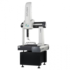
Carry out precision measurements with the Rapid-I System quickly and easily with the intuitive graphical interface. The software comes standard with a bundle of geometric measurement tools, including distances, coordinates, concentricities and line-line angles. These tools are extensively used for measuring bore diameters, component dimensions, champher diameter/angles, tool run-outs, concentricity/offsets, etc on any type of component.
Product Description
Carry out precision measurements with the Rapid-I System quickly and easily with the intuitive graphical interface. The software comes standard with a bundle of geometric measurement tools, including distances, coordinates, concentricities and line-line angles. These tools are extensively used for measuring bore diameters, component dimensions, champher diameter/angles, tool run-outs, concentricity/offsets, etc on any type of component.
Further, advanced features such as software assisted-focusing enables depth measurements in the Z-Axis, XZ/YZ projection measurements in 2-D (this can be used for measuring the angle of a cone, diameter of a spherical shape etc) ; thread tool that enables analysis of external threads for effective diameter/pitch; and thePCD tool enables generation of pitch circles, and automatically calculates angle between different PCD members, and offsets of each member from the PCD.
Custom measurement tools can be easily developed for your components. Measurements can be further accelerated by the use of fixtures, and the software has the Reference Entity feature, that remains constant throughout the measurement session. Hence only part of the point-picking is required for completing the measurement, thus reducing the effort and time required for measurements.
Specification
Model: V2015 V4020
| Form Factor & Aesthetics | LX(Light & Compact) CX(Clasic) |
||
| Video Source Magnification (On a std 17th Monitor) [Working Distance] |
RapidCam-MD(800 x 600) 11-67X (default); [90 mm] 22-134X (with 2X Lens) [36 mm] 55-30X (with 10X Lens) [33 mm] 2X Digital [-NA-] |
||
| Lighting | Cool solid- state LEDs Quarda-zone Surface + Collimated Profile Lighting Variable Intensity/Programmabaility through software Coaxial Lighting Auxilliary flexible lighting |
||
| Worstage Size (X x Y) (mm) Maximum Job Weight (Kg) Measuring Travels(X x Y x Z) (mm) Motion Control |
Continously variable analog joystick for 3+1 (free) axis control. Fully-automatted CNC with Auto-Focuc. |
375 x 220 5 200 x 150 x 150 |
544 x 362 5 400 x 200 x 150 |
| Linear Scales | 0.5µm non contact tape encoders Higher Resolution on order |
||
| Accuracy | within (3+L/100) µm(L in mm) | ||
| Fixture Holding | T-Slot CNC – Drilled / Trapped hole on Workstage |
||
| Software Cross-Hair |
Live-Scan, FrameGrab (automated Edge Detection), Multi-Scan with Focus. |
||
| Geometric Tools | Shapes Standard Point, Line, Circle Arc, Plane, sphere Constructed Mid-Point, Parallel/perpendicular lines, angle bisectors, tangents, Circles with centre, parallel arcs, pin-over dia, nearest/farthest points, cloud points, indexing etc. Measurements Standard Distance (point-point, point-line, point-circle, line-circle, circle-circle), Angle, Radius, Diameter, Circularity Advanced PCD, Thread, Depth, Projections |
||
| DRO | Standard on-screen with Reset & UCS (user-defined). Polar Coordinates possible. |
||
| Graphics | Graphics-on-Video (real-time overlay), CAD (import/edit/export .dxf), Digital Micrometer (onscreen), FasTrace, Digital protractor, Fixed, Text |
||
| Report | Direct Reports in MS Excel with conditional formatting. Graphical Reports plus overlay on component image. Point-cloud files in DXF and delimited Text formats. |

